
Anti-Collision Analysis
Wellbore Separation and Anti-Collision Analysis
Evaluate planned wellpaths against selected offset wells using center-to-center distance, separation factor, and positional uncertainty calculations.
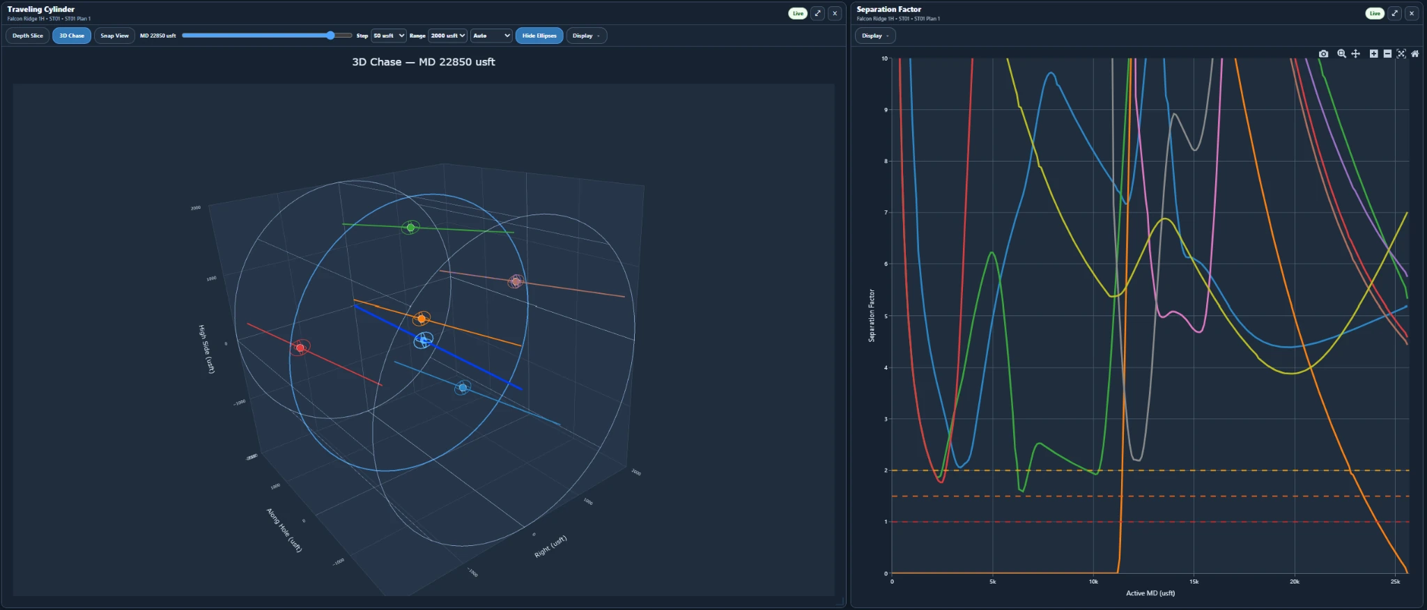
Review separation results along measured depth, examine wellbore geometry using 3D Chase, and assess positional uncertainty using survey error models benchmarked against ISCWSA reference cases.
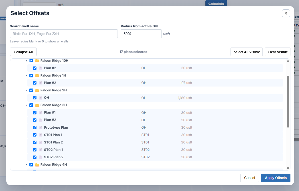
Select offset wells for comparison
Search nearby wells, filter by radius from the active surface location, and choose the specific plans or sidetracks to include in the anti-collision analysis.
DirectionalPlan organizes offsets by well and design so you can review the selection before calculating center-to-center distance, separation factor, and 3D chase results.
- Radius-based well filtering from the active SHL
- Search and review offsets by well, wellbore, and plan
- Bulk actions for selecting or clearing visible results
- Supports multiple plans and sidetracks in one review
Engineering Verification
Benchmarked Against ISCWSA Reference Calculations
Published ISCWSA survey uncertainty and clearance examples compared with DirectionalPlan calculations.
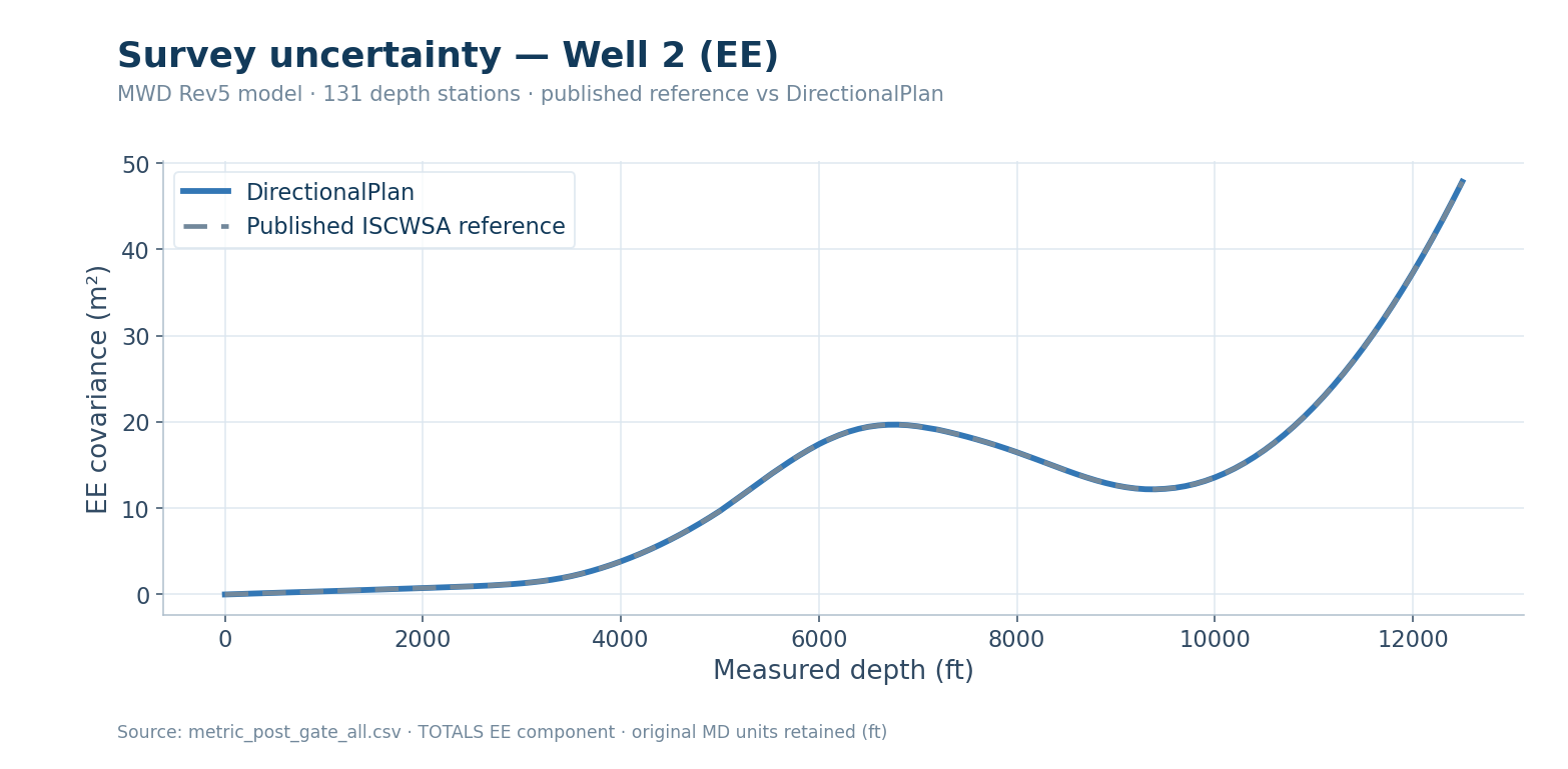
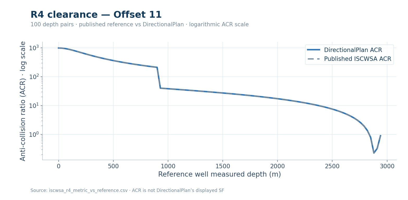
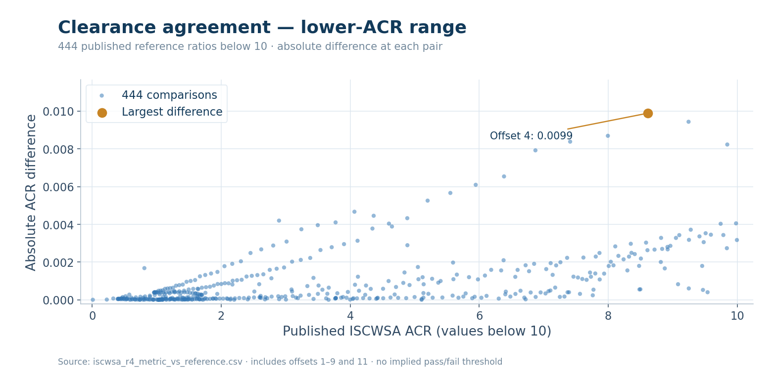
DirectionalPlan-performed reference comparisons, not ISCWSA certification
Test scope and limitations
One Well 1 NE covariance check at MD 1,620 m remains outside the applied tolerance. The supplied R4 comparison data covers offsets 1–9 and 11. ISCWSA ACR and DirectionalPlan's displayed SF use different calculations.
Separation Results
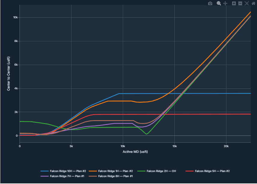
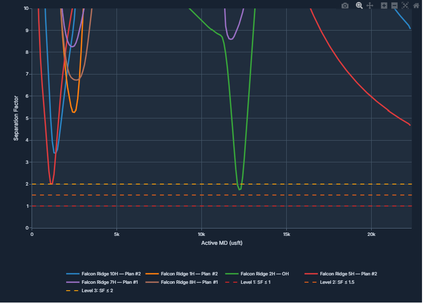
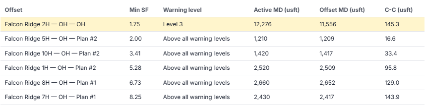
Center-to-Center Distance and Separation Factor
Review centerline distance, separation factor, and offset-specific results along the active wellpath.
Falcon Ridge — Example Anti-Collision Results
Survey Uncertainty
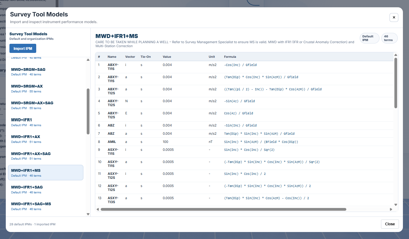
Survey Error Models and Positional Uncertainty
Inspect instrument performance models and visualize calculated positional uncertainty along directional wellpaths.
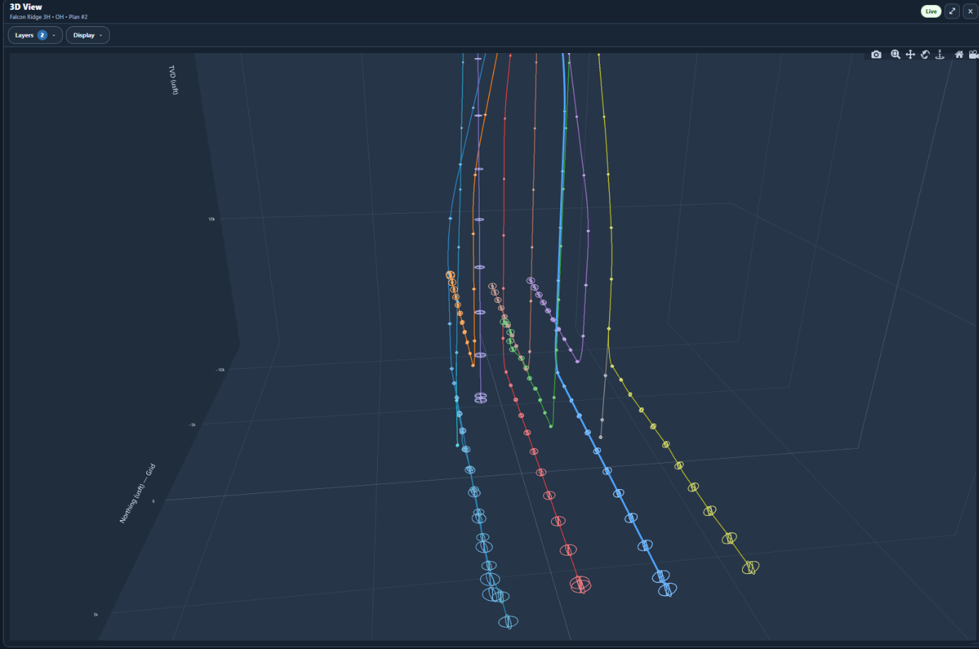
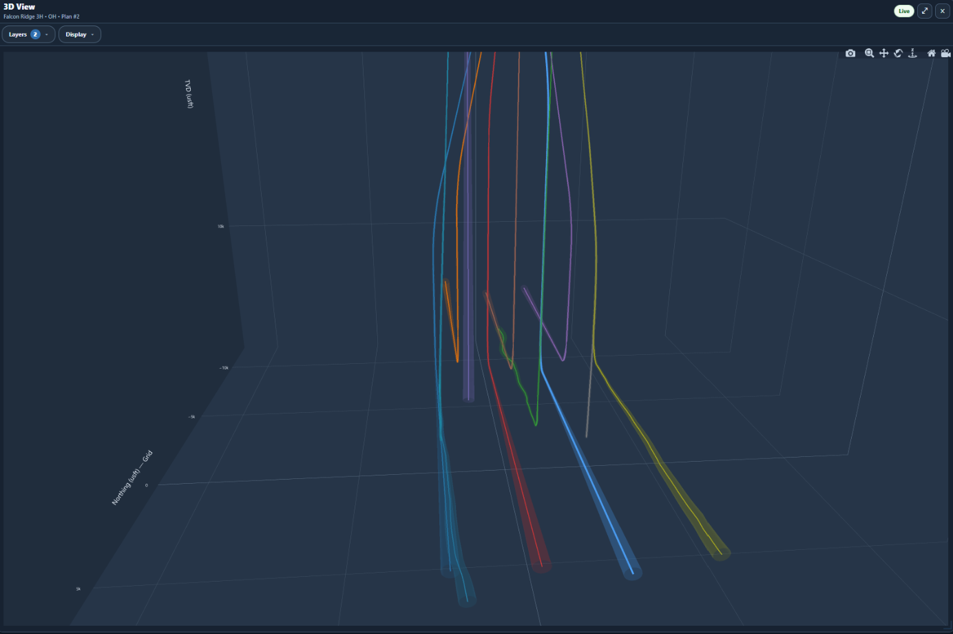
Ellipse rings and smooth envelopes are two ways to display modeled positional uncertainty, not physical wellbore diameters or separate collision-risk calculations.
Spatial Anti-Collision Analysis
Traveling Cylinder and 3D Chase
Inspect the relative positions of selected offset wells at specific measured depths using Depth Slice and 3D Chase views.
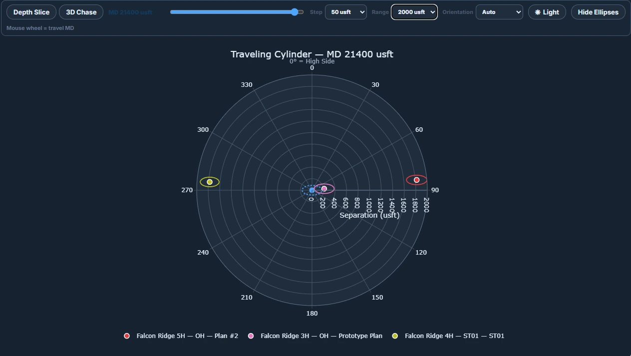
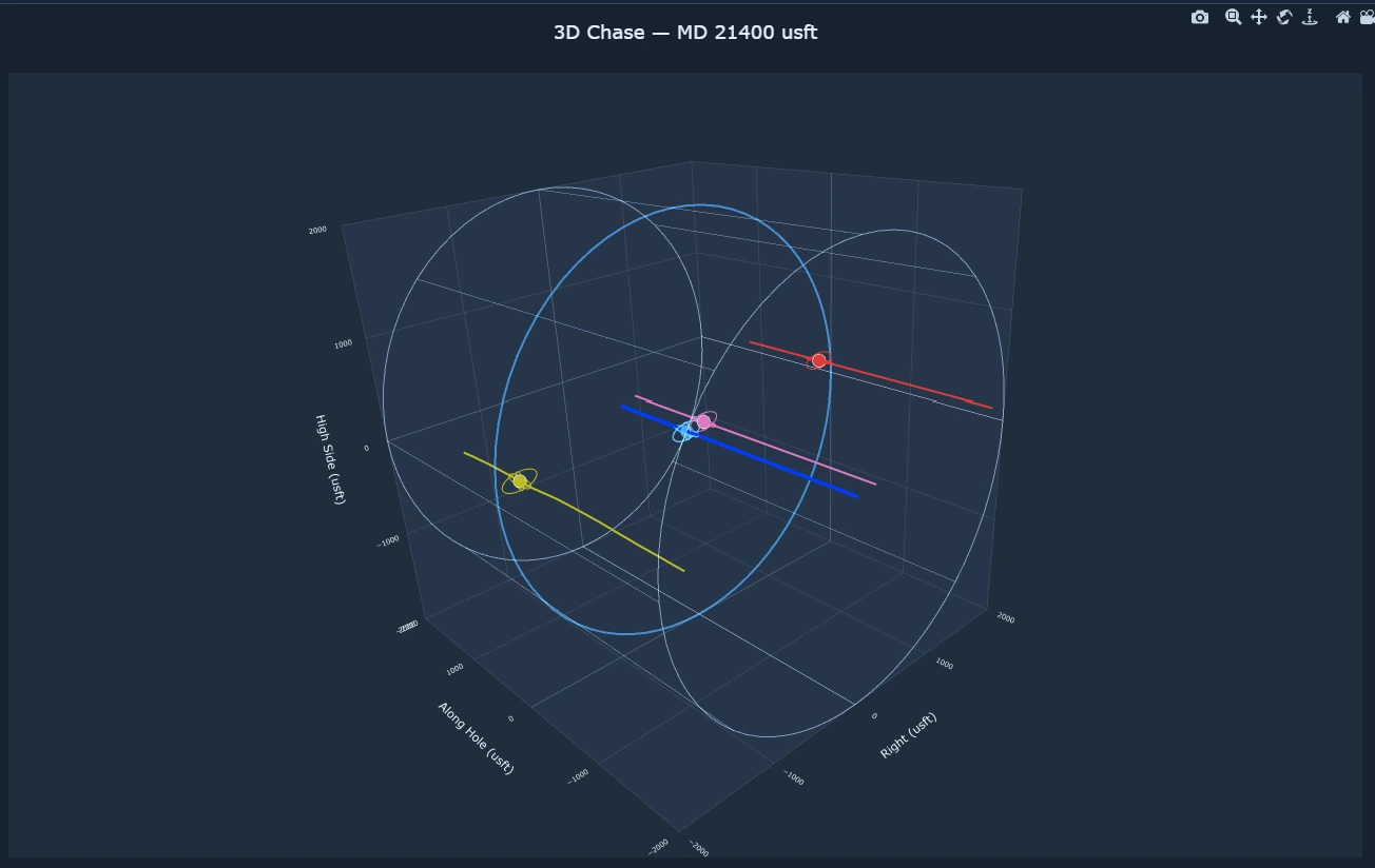
Depth Slice and 3D Chase provide spatial views of selected wellbores. They supplement the center-to-center and separation-factor calculations used for engineering review.
Engineering Reports
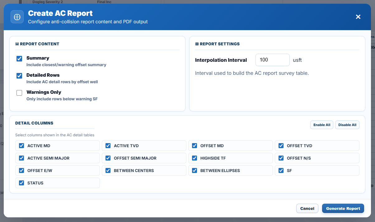
Anti-Collision Reports
Generate PDF reports containing an offset well summary, detailed separation results, and applicable warning levels. Include all calculated rows or limit the report to warning-level results.
Choose the interpolation interval and report columns, including measured depth, center-to-center distance, ellipse dimensions, separation factor, and status.
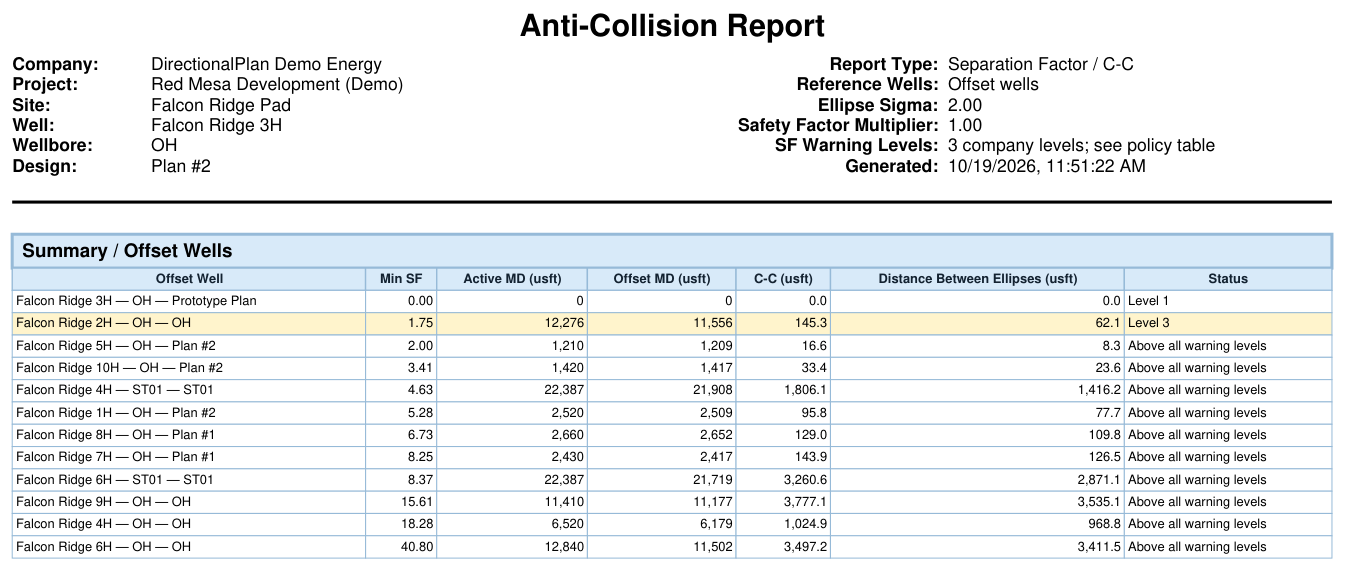 Falcon Ridge 3H
Example Anti-Collision Report · PDF
View Example Report →
DirectionalPlan
Explore the Anti-Collision Tools
Open the browser demo to explore the planning interface, or create a free account to access the complete platform.