7 Wells
Matched DirectionalPlan and MagVAR corrected positions.
 Explore Demo
Engineering Validation
DirectionalPlan survey corrections were evaluated using simulated wells where the raw survey data and well headers were provided first, and the simulated true bottom-hole locations were reviewed only after the correction had already been calculated.
That makes this a meaningful blind-position test: the engine was asked to correct the survey from the measurements alone, then the resulting bottom-hole position was compared against the withheld simulated truth.
Blind Validation Method
The correction solver did not use the simulated true bottom-hole location to produce the corrected survey. The true BHL was only examined after the corrected position was already calculated.
DirectionalPlan took the supplied raw survey data and well header information, calculated a corrected survey, and then checked whether the corrected bottom-hole location moved closer to the independently generated simulated truth.
This is the kind of evidence that helps build trust because it evaluates the final engineering outcome — improved well position — instead of only comparing intermediate calculation steps.
The comparisons below examine independently produced correction results alongside DirectionalPlan outputs. Known-position accuracy and agreement between correction providers are reported as separate engineering evaluations.
Raw MWD survey data and well headers are loaded into the correction workflow.
The correction engine fits sensor and reference effects without using the true BHL.
The calculated corrected bottom-hole position is recorded before truth is reviewed.
3D error is calculated from Northing, Easting, and TVD difference to the simulated known position.
Commercial Engineering Cross-Checks
Independently calculated corrected survey positions were compared using common wellpaths and matching final measured depths. Differences are measured in three dimensions using Northing, Easting, and TVD.
Matched DirectionalPlan and MagVAR corrected positions.
Mean three-dimensional BHL separation.
Median three-dimensional BHL separation.
Seven matched commercial survey datasets. Scale: 0–80 U.S. survey feet. Smaller values indicate closer agreement.
| Case | Final MD (ft) | Raw BHL Difference (ft) | Corrected BHL Difference (ft) |
|---|---|---|---|
| 01 | 22,188 | 0.19 | 8.15 |
| 02 | 22,136 | 0.10 | 3.85 |
| 03 | 19,834 | 1.11 | 8.04 |
| 04 | 18,159 | 1.34 | 77.01 |
| 05 | 21,110 | 0.17 | 34.86 |
| 06 | 27,809 | 0.34 | 36.96 |
| 07 | 22,933 | 1.85 | 33.87 |
The raw-position differences show agreement between the two original survey reconstructions. Corrected-position differences reflect independently applied processing methods and are not measurements against a known true wellbore position.
Known-Position Comparison
Eight simulated well cases were evaluated against known bottom-hole positions using DirectionalPlan and a supplied SuperiorQC comparison dataset.
Each value represents the three-dimensional distance between the corrected BHL and the simulated true BHL. Lower values indicate better positional agreement with simulated truth.
DirectionalPlan mean 3D error (source units)
SuperiorQC mean 3D error (source units)
DirectionalPlan closer in 2 cases; SuperiorQC closer in 6 cases.
Eight anonymized simulated wells. Blue bars represent DirectionalPlan; green bars represent SuperiorQC. Scale: 0–80 source coordinate units.
| Case | Azimuth | DirectionalPlan Error | SuperiorQC Error | Closer to Truth |
|---|---|---|---|---|
| S01 | 0° | 15.31 | 8.11 | SuperiorQC |
| S02 | 0° | 2.86 | 1.94 | SuperiorQC |
| S03 | 30° | 23.67 | 12.46 | SuperiorQC |
| S04 | 30° | 39.06 | 26.08 | SuperiorQC |
| S05 | 60° | 42.24 | 74.18 | DirectionalPlan |
| S06 | 60° | 29.81 | 20.92 | SuperiorQC |
| S07 | 90° | 2.66 | 35.00 | DirectionalPlan |
| S08 | 90° | 25.83 | 20.23 | SuperiorQC |
These eight historical simulated cases are separate from the 80-well blind-validation cohort shown above. The numerical comparison uses the supplied recorded errors. The original source units and prediction-freeze sequence for this separate dataset have not been independently confirmed.
Three-Way Case Study
A single well was processed using DirectionalPlan, MagVAR, and SuperiorQC corrected survey methods. The resulting final-position differences provide a direct comparison of the three calculations.
DirectionalPlan vs. SuperiorQC
DirectionalPlan vs. MagVAR
MagVAR vs. SuperiorQC
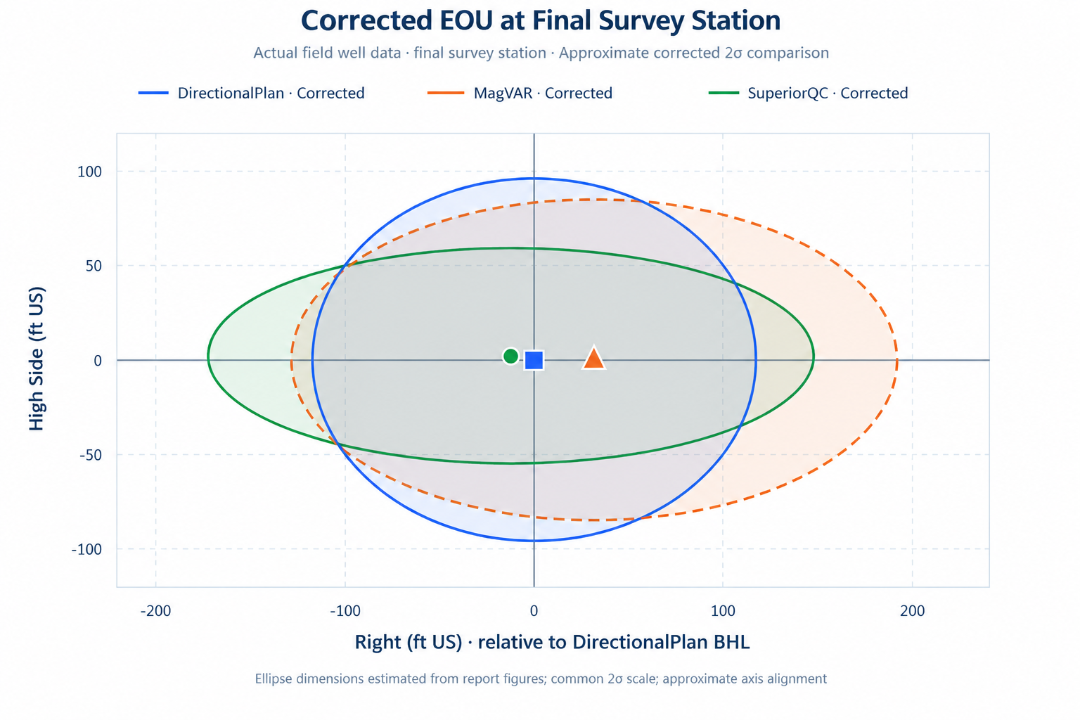
Three-way case study: final MD 22,933 ft US. The supplied SuperiorQC report was generated in a non-production environment and is marked not definitive. Processing methods differ, including SAG and FDIR handling. These comparisons do not establish which corrected position is closest to actual wellbore truth.
Commercial provider names identify the origins of the reference calculations. No certification, partnership, or endorsement by those providers is implied. Original third-party survey deliverables are not reproduced on this page.
Correction Method
The technical guide describes a physics-based correction workflow. The correction is calculated from the measurements and references — not by forcing the survey to a desired bottom-hole location.
Total magnetic field, dip, declination, gravity, and grid convergence are checked against the survey location and date before correction is accepted.
The engine evaluates plausible sensor and reference error combinations using the gravity and magnetic measurements recorded through the survey run.
Supported corrections are applied to recompute inclination, azimuth, and the resulting trajectory by minimum curvature.
Positional uncertainty is still an engineering estimate. A corrected survey may become more plausible without claiming certainty beyond what the data supports.
DirectionalPlan has also been reviewed against dozens of independently corrected survey deliverables from established providers. Those files are used as internal engineering cross-checks and are not republished here because they are proprietary.
This page includes blind-test improvements and regressions, numerical comparisons with commercial correction results, uncertainty-model limitations, and the beta status of the feature.
What This Evidence Means